
 ">WeChat
I. SAFE AREAS
The perimeter of the firewall includes a safe area and a secure space.
Security area
Within the firewall, a security area (Security Zone), referred to as a zone (zone), is a combination of one or more interfaces that contain the same security attributes for users.
The equipment considers that data flows within the same safe area are credible and do not require any security strategy. Only when there is a flow of data between different secure areas will security checks be triggered against firewalls and corresponding security strategies implemented.
Secure area.
Any two safety areas constitute a secure area (Interzone) and have a separate security space view, most of which is configured under the secure area view.
For example, when a security area is configured Zone1 and Zone2, in the secure inter-domain view of Zone1 and Zone2 you can configure ACL package filters to indicate that ACL package filters are implemented for data flows occurring between Zone1 and Zone2.
After the power firewall function in a secure area, when high-priority users access low-priority areas, the firewall records information on the message ‘s IP, VPN and so forth, generating a flow chart. When the message returns, the device looks at information such as IP, VPN and so forth, because it contains messages that send messages, there are tables to which the return report passes. Low-priority users have defaulted that they will not be allowed access to the higher-priority user area. Thus, the Intranet is set up as a high-priority area, the extranet is set as a lower priority area, the insider has active access to the outside network, while offline users are unable to access them.
Advantages of firewalls based on secure areas
The strategic configuration of traditional switches/routers is usually built around the input-entry interface, out of which the firewall has evolved gradually to move away from a role that connects only external and intranet networks, with an Intranet/extranet/DMZ (Demilitarized Zone) model and moving in the direction of providing high port density. In this network environment, traditional interface-based tactical configuration places a huge burden on network administrators, and security strategy maintenance workloads have multiplied, increasing also the probability that deployment will introduce safety risks.
In addition to complex interface-based security policy configurations, some firewalls support the overall strategic configuration. The disadvantage of a global strategy configuration is that it has to be thickly configured, one device can only be equipped with the same security strategy and does not meet users ‘ requirements for different security strategies in different safety areas or interfaces, which have obvious limitations on use.
Firewalls based on secure areas support a security area-based configuration, with all attack detection strategies deployed in the safe zone, which are simple and flexible, both to reduce the burden of network administrators and to meet the requirements for different strike preparedness strategies for a safety area under complex cluster conditions.
II. FIGHTSHOT METHODOLOGY
In order to increase the flexibility of the firewall network, equipment no longer defines working patterns for the entire device but rather work modes for interfaces, which are as follows:
Route mode:If the device interface has an IP address that is connected to the outside through three layers, it is considered to work in route mode.
Transparent mode:If the device interface has no IP address to connect through a two-tier external connection, it is considered that the interface works in transparent mode.
If the device has both an interface working in route mode (the interface has an IP address) and an interface working in transparency mode (the interface does not have an IP address), it is considered that the device works inMixed ModeDown.
1. Route mode
When the equipment is located between an internal network and an external network, each of the IP addresses of the different segments of the network are configured for interfaces with an internal network or an external network, and the original network pounce structure is reprogrammed.
As shown in the graph, two safe areas are planned: the Trust and Untrust regions, the Trust regional interface for equipment is linked to the company’s internal network, and the Untrust regional interface is connected to the external network.
Note that the Trust regional interface and the Untrust regional interface are in two different subnets.
Route Mode Group Network Chart
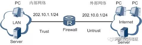
When messages are forwarded between interfaces in three-storey areas, the router is searched according to the IP address of the message. The device is shown as a router. Unlike routers, however, the IP message transmitted by the device requires relevant processing such as filtering and checking tables or ACL rules to determine whether it is allowed to pass. In addition, firewalls require other attack prevention checks.
When you use route mode, you can complete ACL (access control list) filters and ASPF dynamic filters. However, route mode requires modifications to network popping structures, such as changes in gateways for internal network users, changes in route configurations, etc. Before the network is retrofitted, trade-offs should be made.
2. Transparency model
If the equipment works in a transparent mode, changes to the extended structure can be avoided. At this point, the device is completely transparent for subnet users, who do not feel it exists.
The typical grouping mode of the equipment transparency model is shown in the figure. The Trust regional interface for devices is connected to the company’s internal network, and the Untrust regional interface is linked to the external network. Note that the Trust regional interface and the Untrust regional interface must be located within the same subnet.
Transparent Mode Group Networking
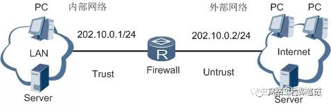
When using a transparent model, you simply insert devices like bridge into the network without changing any existing configuration. IP messages are also filtered and internal network users remain protected by firewalls.
Transparency mode diagram
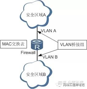
As shown in the figure, Safety Area A and B are connected to Safety Area A and VLAN B on an interactive data interface in the same grid. The interfaces to Security Area A and B are joined by a bridge team consisting of VLAN A and VLAN B, respectively, and must be joined with a bridge unit composed of VLAN A and VLAN B. When the firewall transmits messages between these two transparent modes, it is necessary to first perform a VLAN bridge, convert them into VLAN, then find an interface based on MAC addresses in the message. However, unlike the bridge, equipment needs to be sent to the top level for filtering, etc., through examination of session lists or ACL rules to determine whether the message is allowed to pass. In addition, the firewall will need to complete other attack-prevention checks.
Note:
Requires that two jobs be entered into a different VLAN interface in transparent mode and interactive with data; at the same time, both interfaces must be added to the same VLAN bridge group and only one bridge team.
The device conducts MAC address learning on the transparency mode interface and a second-level transmission by checking MAC tables when transmitting messages between transparent modes.
3. Mixing mode of equipment
If the device works on both an interface in route mode (the interface has an IP address) and an interface in transparency mode (the interface does not have an IP address), it is considered to work under hybrid mode.
Mixed Mode Group Net Chart
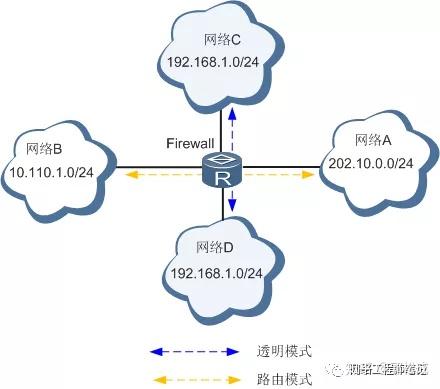
Network A and B are different links, the interface between devices to network A and B is a three-tier interface that links messages between A and B by route; networks C and D are the same grids, the interface between devices to network C and D is a two-layer interface, and VLAN bridge and second-level relays to messages between C and D are performed.
III. FIELD WALLING
The rationale for filtering the firewalls is:
The filter is based on the protocol number, source/purpose IP address, source/end port and message direction that are carried by the IP layer in the package. In transparent firewall mode, it can also be filtered according to the source/ end MAC address of the message, too many types, etc.
Package filtering is applied in firewalls, where data packages that need to be forwarded are obtained first with header information and then compared with the set ACL rules, which determine whether to forward or discard the package based on a comparison.
Package filter firewalls
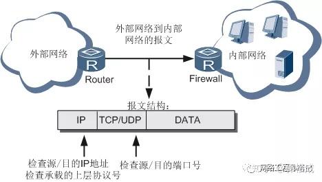
Device support for package filtering firewalls
Common IP filter: Firewall checks and filters the message based on access control list ACL. Firewall checks the source/ destination IP address, source/purpose port number, protocol type number of the message, allows passage of the eligible message according to the access control list and rejects messages that do not match the condition. Firewall checks sources of information are in IP, TCP or UDP headers.
Second-tier filtering: A transparent firewall can check and filter a second-level report based on access control list ACL. The firewall checks the source/ purpose of the message, MAC, or too-type fields that allow passage according to the access control list and reject messages that do not meet the matching requirements. The information from the firewall is at the head of MAC.
Sub-report filter: The package filter provides support for the detection filtering of sub-files. The package filtering wall will identify the type of message, e.g. a non-separation report, a copy of the first film, a follow-up feature, which filters all types of paper. For the first piece, equipment matches the ACL rule with three layers of information and four layers of information, and if passed, records the status of the first piece, creating a matching table for subsequent sub-sections. When the follow-up sub-issue arrives, the firewall no longer matches the ACL rules, but forwards them on the basis of the ACL matching results of the first sub-filtration. Furthermore, for those reports that do not match the ACL rules, the firewall can also configure default processing.
IV. STATE FIGHTS
The package filters the firewall, which is static, and the current problems are as follows:
Some of the security policy configurations cannot be foreseen for multi-channel application layer protocols (e. g. FTP, SIP etc.).
It is not possible to detect certain attacks from the transmission and application layers (e.g. TCP SYN, Java Applets).
Unable to identify the false ICMP misperceptions from networks, it is impossible to avoid malicious attacks by ICMPs.
For TCP connections, both initial submissions are required to be SYN and first TCP packages that are not SYN will be discarded. In this way, when equipment is first added to the network, non-first packages of original TCP links are discarded while newly added firewalls are being added, which would interrupt existing connections.
Thus, the concept of a state firewall – ASPF (Application Special Packet Filter) is proposed.
Application layer protocol testing, including FTP, HTTP, SMTP, RTSP, H.323 (Q.931, H.245 and RTP/RTCP);
Transfer layer protocol testing, including TCP and UDP tests, i.e. universal TCP/UDP tests.
ASPF function
The main functions of ASPF are as follows:
Enables to check application layer protocol information, such as the type and port number of the message, and monitors the status of the interface-based application layer protocol. For all connections, each connection information will be maintained by ASPF and used dynamically to determine whether data packages are allowed into an internal network through firewalls in order to prevent malicious intrusion.
• The ability to detect transmission layer protocol information (i.e., generic TCP/UDP testing) and access to the internal network through firewalls based on source, destination and port decisions TCP or UDP messages.
Other functions of ASPF are:
ASPF not only filters the information according to the state of connection, but also monitors the content of applications and provides a Java Blocing function for untrustworthy sites that protects networks from harmful Java Applets.
Supports the TCP connection first-pack test. Test the initial report of the TCP link to see if it is SYN or not, and decide whether to discard it according to current configuration.
Supports ICMP error detection. Normal ICMP error messages carry relevant information on the corresponding connection to this article, which matches the connection. If matching fails, decide whether to discard the ICMP submission according to current configuration.
Working together at the network boundary, ASPF and package filtering firewalls can provide a more comprehensive and demand-driven security strategy for enterprise internal networks.
ASPF Basic Concepts
Java Blocking
Java Blocing is a blockage of the Java Applets program that is transmitted via HTTP. When Java Blocing is configured, the request command sent by the user to try to access the Java Applets on the Web page will be blocked.
Single-channel and multi-channel agreements
Single-channel protocol: Only one channel is involved in data interaction, e.g. SMTP, HTTP, during the entire process from creation to deletion of a session.
Multi-channel protocols: contains a control channel and several other controls or data channels, i.e. the interaction of controlled information and the transmission of data are performed on different corridors such as FTP, RTSP.
Application layer protocol detection fundamentals
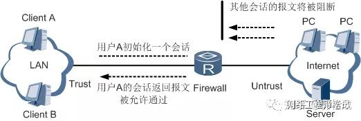
As shown in the figure, to protect an internal network, access control lists will normally need to be configured on a router to allow access to the external network by the host of the Intranet while denying access to the internal network. However, access control lists filter messages returned after the user initiated the connection and thus the connection could not be properly established.
Once the application layer protocol is configured on the device, ASPF can detect each application level session and create a status tabulation and a temporary access control list (Temporary Access Control List, TACL):
1. The status table was created when the first outgoing message is detected by ASPF to maintain the state of a session at a given time and to detect the correct conversion of the session.
A schedule of the temporary access control list is created at the same time as a status table item is created and removed after the session, which corresponds to an extension of the ACL permit entry. TACL is used primarily to match all returns in a session and can create a temporary return channel for returns from one application on the external interface of the firewall.
The following is an example of the multi-channel application layer protocol detection process using FTP testing.
FTP test process diagram
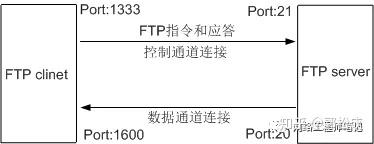
As the figure shows, FTP connections are created as follows: Assuming that FTP connects to the 21 port of FTP server at 1333 port, it is agreed by consultation that the 20 port of FTP servicer initiates a data channel connection to the 1600 port of FTP client and that the data transfer is removed over time or after completion.
The FTP detects the following treatment during the FTP connection to be removed:
1. Checks the IP messages sent out of the interface and confirms them as FTP based on TCP.
Check port numbers to confirm the connection as a control link and create TACL and status tables for returns.
3. Check FTP control connection messages, interpret the FTP command and update status table entries according to the instruction. If you include a data channel to create instructions, create TACL for data connections; no state detection is performed for data links.
4. For returns, matching checks are made according to the type of agreement and will determine whether or not a submission is allowed in accordance with the status table of the respective agreement and TACL.
5. The status table and TACL are deleted when the FTP connection is removed.
A single channel application layer protocol (e. g. SMTP, HTTP) is simpler to detect and TACL is created when a connection is initiated, with the deletion of the link.
Transfer layer protocol detection fundamentals
The generic TCP/UDP detection is a general TCP/UDP test that, unlike the application-level protocol testing, tests are performed on information transmitted from the message layer, such as source, destination address and port number. Universal TCP/UDP testing requires that returns to the ASPF external interface fully match previous messages sent from the ASPF external interface, i.e. sources, purpose addresses and port numbers are matched, otherwise returned reports will be blocked. For multi-channel applications like FTP, H. 323, data connections cannot be established without the direct configuration of TCP detection without an application-level inspection.
V. THE BLACKLOCK
Blacklist is a way of filtering the message according to its source VPN and its source IP address. Compared with ACL, because the field matching is simple, filters can be achieved at very high speed so that messages sent from a given IP address are effectively shielded, while users are supported in static configuration of blacklists and firewall dynamically generating black lists.
As the figure shows, the IP address of user B is already on the blacklist and all messages sent from user B will be discarded by firewalls.
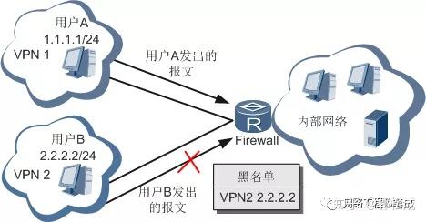
Device support for blacklists
In addition to the static configuration of blacklists, when a specific IP address is found by the device to be active in an IP scan attack or port scan attack, the attacker ‘ s IP is automatically inserted into a blacklist. If the blacklist has been enabled, any message from this IP address can be filtered out for a certain period of time thereafter.
Users can configure the age of static and dynamic blacklists.
Whether or not the blacklisted data package is allowed access under ACL rules, the firewall discards such data packages.
Users can export blacklist configuration information to a file or import blacklist profiles via a file.
VI. White List
The host that adds a white list to the firewall will not be added to the dynamic and static blacklist, using source VPN and IP addresses as a white list item. The white list is mainly used in situations where legitimate business messages from specific devices on the network have IP scanning attacks and port scans of attack characteristics, preventing the particular device from being blacklisted by firewalls.
The white list is static only.
Characteristics of the White List
If the user adds a host’s VPN and IP addresses to the White List, the firewall does not conduct an IP scan attack on the host’s messages or port scan attacks, nor will it generate a dynamic blacklist of its IP address, nor does it allow users to add white list hosts to static black lists.
Device support for white list
When the device receives a message, it checks if it is from a white list item. If so, the device does not conduct an IP scan attack and port scan attack check on that article or generate a dynamic blacklist for source IP, but other security filters such as ACL package filtering, ASPF, traffic statistics and surveillance are still required to achieve maximum safety filtering of firewalls.
Users can configure the age of the white list.
The user can export white list configuration information to a file, or import white list profiles from a file.
Port Map
The application layer protocol usually uses a known port number for communication. Port mapping allows users to define a new set of port numbers for different application level protocols, and also specifies the host range that uses unknown ports.
Port mapping is only meaningful when used in conjunction with business-sensitive features such as ASPF and NAT. For example, internal FTP servers are available through the 2121 port in an enterprise private network. Users can only use 2121 as port numbers when accessing a FTP server via the NAT server.
Since the port number of the FTP message is 21 by default, the FTP server will not be able to recognize the 21 port message as an FTP application. On this occasion, a port map will need to be used to map the 2121 port into an FTP protocol, and the NAT server will transmit the 2121 port message as a FTP protocol message to the FTP server to enable access to the FTP server.
Device support for port mapping
Device support for port mapping is achieved through ACL, which only occurs when matching a message from an ACL. The port image uses the basic ACL (Nos 2000-2999). When filtering messages using ACL, the port map matches the IP address configured in the basic ACL rules with the purpose IP address of the message.
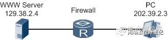
As shown in the figure, external PC access to internal WWW servers via Router (port number 8080) and when external PC messages pass through Router, a hit ACL message will be used for port mapping, which can only be done by Router with an address of 129.38.2.4.
Port Map
VIII. Attack preparedness
Types of cyberattacks
Cyberattacks generally fall into three main categories: denial-of-service attacks, scanned spy attacks and deformations:
1. Denial of service type attacks
The denial service-type DoS attacks are the use of a large number of data packages to attack systems, preventing them from accepting normal user requests or suspending the host for irregular work.
The difference between denial of service attacks and other types of attack is that the attackers do not seek access to internal networks, but rather prevent legitimate users from accessing resources or firewalls.
2 Scan and spy attacks
Scan and spy attacks are systems that use ping scans (including ICMPs and TCP) to identify survival on the network, thus identifying potential targets accurately. Port scanning using TCP and UDP etc. allows detection of types of operating systems and potential service categories.
By scanning and spying, the assailants are able to obtain an overview of the type of services provided by the target system in preparation for further intrusion into the system.
3. Deformed attacks
The malformations attack is the sending of defective IP messages to target systems, causing a breakdown in the target system when dealing with such IP packages, resulting in damage to the target system. The main deformities are Ping of Death, Tedrop, etc.
Equipment support for attack prevention:
Land, attack.
Land attacks are the setting of the source and destination IP addresses for the SYN package of TCP. This will result in the target computer sending its own SYN-ACK message, and the target computer sending back an ACK message to itself and creating an empty connection, each of which will remain open until it is overtime.
Land, attack pattern.
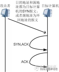
Different kinds of hosts react to Land attacks, many UNIX hosts collapse and Windows NT main opportunities become extremely slow.
Smurf Attack
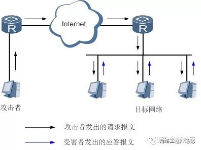
A simple Smurf attack is used to attack a network. The assailant sends the ICMP response request message to the target network, which has the targeted address set out at the broadcast address of the target network, so that all hosts of the target network respond to this request and cause web congestion.
Simple Smurf attack graph
Advanced Smurf attacks are used primarily to attack the target host. The assailant sends an ICMP response request to the network where the target host is located, and the source address of the message is set at the address of the target host so that all responses will be sent to the target host. Ultimately, the target host is slow to process or even collapse.
Advanced Smurf attack graph
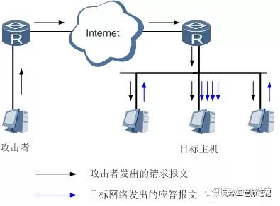
Smurf attacks take a certain amount of traffic and duration to deliver the message in order to actually constitute an attack. In theory, the more hosts the target network, the greater the impact of the attack.
WinNuke Attack
NetBIOS is a basic web resource access interface that is widely used for file sharing, print sharing, inter-process communication (IPC), and data exchange between different operating systems.
In order to achieve NetBIOS on the TCP/IP protocol stack, the RFC sets out a series of interactive criteria and several commonly used TCP/UDP ports as follows.
139: TCP port for NetBIOS session service.
137: UDP port for NetBIOS name services.
136: UDP port of NetBIOS data reporting service.
Windows operating system has achieved NetBIOS over TCP/IP functionality and opened the 139 port.
WinNuke’s attack was a loophole in the Windows operating system, sending messages to this 139 port with TCP data outside, but unlike those that normally carry OOB data, their pointer fields do not match the actual location of the data, i.e. overlap and when Windows operates these data collapse.
SYN Flood Attack
SYN Flood attacks use a loophole in TCP three handshakes to launch an attack on the target computer. The assailant sends a request for TCP connection (SYN) to the target computer, and then does not respond to the SYN-ACK report that the target returned. If the target computer does not receive a response from the attackers’ ACK, it will wait until half of the connection is released.
Semi-connector Icon
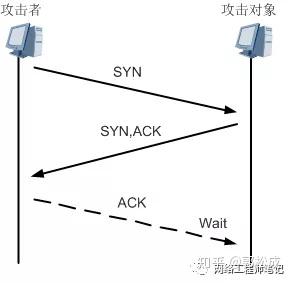
In this way, the attackers send a large number of TCP SYN messages, which allow the target computer to generate large numbers of semi-connected connections, forcing it to waste its vast resources on these half-connected links. Once the target computer has exhausted its resources, there are situations where the target computer is very slow and normal users cannot access them.
The attackers can also forge a SYN newspaper with a false or non-existent address and launch an attack on the target computer.
ICMP Flood Attack!
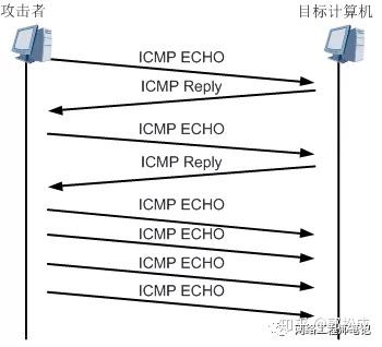
Normally, network administrators use PING programs to monitor and troubleshoot networks, as follows:
The source computer sends an ICMP response request (ICMP ECHO) to the recipient computer.
2. Once the computer has received a response from ICMP to the request, it responds to an ICMP response (Echo Reply).
This process needs to be handled by the CPU, and in some cases it may consume significant resources.
If the attackers send a large number of ICMP ECHO messages to the target computer (which generated the ICMP flood), the target computer is busy processing these ECHO submissions and cannot continue with other data reports.
ICMP Flood Attack Map
UDP Flood Attack!
The rationale of the UDP Flood attack is similar to that of the ICMP Flood attack, where the attackers were unable to continue with normal communications by sending a large number of UDP messages to the target computer, which caused the target computer to be too busy processing these UDP reports.
Address scanning and port scanning attackors use scanning tools to detect target addresses and ports, which respond to such detections, using them as a basis for determining which target systems are alive and connected to the network, which portals are open or closed.
Ping of Death Attack
Ping of Death is an attack on the system using some oversized ICMP newspaper.
The length of IP message is 16 bits, which indicates that the maximum length of an IP submission is 65535. For ICMP responses to requests for information, if the data are longer than 65507, it makes ICMP data +IP head length (20) + ICMP head length (8) > 65535. For some firewalls or systems, after receiving a message of this type, the failure to process them causes a system collapse, death or restart.
ICMP Super-high profile diagram

Large-ICMP attack
Similar to ping of death, Large-ICMP is an attack on the system using some large ICMP newspaper that, unlike ping of death, does not exceed the maximum length of IP paper 65535 but also causes cracks in some operating systems.
The maximum length of ICMP messages allowed to pass needs to be configured on the firewall.
ICMP-Unreachable Attack
Some systems are considered to be directly unattainable for subsequent messages sent to this destination upon receipt of an ICMP that is not available on the Internet (file type field 3 and code field 0) or on a mainframe (mail type field 3 and code field 1).
ICMP-Unreachable attack graph
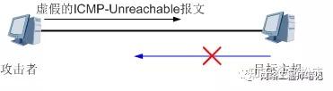
Using this mechanism, the attackers sent false ICMP-Unreachable messages to the target host, disrupting the route information of the target host and influencing its transmission.
ICMP-Redirect Attack
The ICMP-Redirect attack is similar to the ICMP-Unreachable attack.
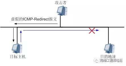
The network device can send an ICMP re-direction message to the host of the same subnet, requesting the host to modify the route.
Using this principle, the attackers sent false re-directional messages across the web to the target host of another network in order to change the route chart of the target host.
The attack interfered with the route information of the target ‘ s mainframe and affected the delivery of messages.
ICMP-Redirect attack graph
IP-fragment attack
Several fields in the IP paper are relevant to the segment: DF (Don’t Fragmentate) bits, MF bits, Fragment Ofset and Length.
If there is a contradiction in the values of the above-mentioned fields and the equipment is not properly handled, it may have some impact on the equipment or even be paralysed.
The DF position is set, while the MF position is set at the same time or the Fragment Ofset is not zero.
DF position 0, and Fragment Ofset+ Length > 65535。
In addition, since the presentation of a feature would increase the burden of buffering and restructuring equipment for the purpose, it should be dropped directly as part of the sub-section of the device itself.
Tedrop Attack
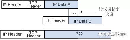
In the course of a network transfer, a fraction is performed if an IP message exceeds the length of a chain-level MTU (max transfer unit). In the header of the IP report there is a offset field (OFFSET) and a subscript (MF), which indicates that the IP message is a subset of a large IP package, where the deviation indicates the location of this clip in the entire IP package. The receiver can restore the IP package based on this information from the header.
For example, when a larger paper is transmitted on the smaller MTU chain, it is divided into two IP papers that will be assembled at the end of the destination and returned to the original IP message.
Normal sub-section profile
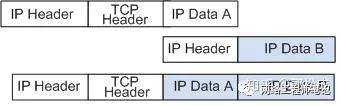
If an attacker breaks this normal situation and sets the deviation field to incorrect values, i.e. there may be overlaps or break-ups. Some TCP/IP composures collapse when they receive a fake subs like these with overlapping deviations, which is known as Teardrop attacks.
Teardrop attack graph
Fraggle attack.
The rationale for the Fraggle attack is similar to that of the Smurf attack, however, the Fraggle attack sent a UDP rather than an ICMP. Because it sent a UDP message, the Fraggle attack could go through some firewalls that prevented the ICMP report from entering.
The rationale used for the Fraggle attack is that both UDP port 7 (ECHO) and port 19 (Chargen) will respond when they receive a UDP message.
Upon receipt of the message, UDP port 7 will respond to what is received like ICMP Echo Reply.
Upon receipt of the message, UDP port 19 produces a stream.
Both UDP ports generate a large number of responses, crowding out network bandwidth.
The attacker can send UDP messages to the network in which the target host is located with an address that originates from an attack on the host, or a broadcast address or subnet address where it is located. The end port number is 7 (ECHO) or 19 (Chargen). Each system that activates this feature sends a response message to the affected host, thus generating significant traffic and causing congestion in the network or collapse of the host.
If these features are not activated by the host(s) of the target host network, they will generate an ICMP message that is inaccessible and still consume bandwidth. The source port can also be changed to port 19 (Chargen), with a destination port of 7 (ECHO), which automatically produces responses that are more harmful.
Tracert attack
Tracert is a source of ICMP overtime returns on TTL (Time To Live) and an unattainable ICMP port returns upon arrival to find the path to the destination.
The attackers can use Tracert to pry into the network structure. It’s potentially dangerous for the network.
Malformed TCP newspaper attack
The TCP submission was the result of an error in processing the recipient TCP bond by deliberately missetting six markers in the head of TCP to achieve the purpose of the attack.
IX. Flow statistics and monitoring
The firewall not only monitors data flows, but also monitors the launch of connections between internal and external networks, which are heavily statistically calculated and analysed. The wall’s statistical analysis can be followed by post-analysis of log information through specialized analytical software, on the one hand, and the firewall system itself can perform part of its analytical functions with some real time properties.
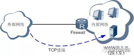
For example, an analysis of whether the TCP/UDP connections initiated by an external network have exceeded the set threshold can determine whether there is a need to limit the launch of new links in that direction or to restrict the initiation of new connections to an IP address of an internal network.
The figure is a typical example of the application of firewalls, where an external network is activated with an IP-based analysis function to the internal network. If the TCP connections initiated by the outside network to the Web server 129.1.9.1 exceed the established threshold, it will limit the ability of the external network to initiate new connections to the server until the number falls into normal range.
TCP Extra-Specific Numbers of Connections
The equipment-supported flow statistics and monitoring methods are as follows:
System-level traffic statistics and monitoring
System-level traffic statistics and monitoring take effect for all system-wide secure inter-domain data streams with firewall functionality, i.e. devices measure the number of connections between ICMPs, TCPs, UDPs, etc. across all security domains. When a connection exceeds the configuration threshold, equipment takes measures to limit connectivity until the connection falls below the threshold.
Traffic statistics and monitoring based on safe areas
Based on the flow statistics and monitoring of a safe area, data streams between this and other secure areas are effective, i.e. equipment will measure the total number of TCPs, UDPs, etc. connected between this safe area and all other secure areas. When the total number of connections established between this safe area and all other secure areas or in one direction exceeds the assigned threshold, the device will take measures to limit connection numbers until the number of connections falls below the threshold.
Traffic statistics and monitoring based on IP addresses
Based on the flow statistics and monitoring of IP addresses, a TCP/UDP connection is used to measure and monitor a single IP address in a security area. By analysing whether the total number of TCP or UDP connections received by the source IP address or by the purpose address exceeds the established threshold, it can be determined whether there is a need to limit the launch of new links in that direction in order to prevent malicious attacks on systems or denials of services due to the system being too busy.
When the TCP/UDP connection falls below the threshold, the source IP address or destination address can be restarted or accepted for TCP or UDP connections.
Firewall logs
Firewalls can record the movement and state of firewalls in real time (e.g. some kind of firewall measures, detection of a cyber attack, etc.) and record information in logs.
The analysis and archiving of the log content enables managers to check for firewall security holes, when someone is attempting to break security tactics, types of cyberattacks, and real-time log records can also be used to detect ongoing incursions.
The firewall log function can be configured when the movements and state of the firewall need to be recorded in order to check for security gaps, detect cyberattacks and intrusions.
Device support for firewall logs
Blacklist Log
When an address scan, port scan etc. is detected, the device dynamically generates a blacklist log when it is enabled to do so.
The blacklists that are added manually also generate blacklist logs.
A dynamic blacklist, a static blacklist that is manually added to the list, produces a de-blacklist log after an ageing time.
Attack Log
When equipment is found for various types of attack, it produces an attack log that records the type and parameters of attack.
Flow Control Log
The device generates traffic monitoring logs when the number of conversations in the system as a whole, and regional accesses, exceeds the ceiling of the assigned connectivity threshold, and when the number of sessions falls below the lower limit of the configured connection threshold, the device produces flow recovery logs.
Stream Log
The device’s flow log is used to encapsulate the flow log information and send it to the log server in an ageing session.
XI. VIOLENT FALLS
Small private networks have been growing in recent years, and they are generally geared to small businesses.
There is a strong need for security precautions.
Financially, it is not possible to afford a dedicated security facility.
Equipment support is logically divided into virtual firewalls, which provide independent security for a number of small private networks.
Each virtual firewall is a combination of VPN-Instance, security examples. It provides private route transfer plane and security services for the users of the virtual firewall
VPN Example
The VPN example provides a separate VPN route for virtual firewall users, corresponding to the virtual firewall.
Security Examples
Security examples provide separate security services for virtual firewall users, which correspond to the virtual firewall. These safety examples have private interfaces, safe areas, secure spaces, ACL and NAT rules, as well as private security services such as blacklists, filtering of packages, traffic statistics and monitoring, attack prevention, ASPF and NAT for virtual firewall users.
XII. Firewall mains
Firewall equipment is a single point through which all information flows must pass, and any flow of information that breaks down in the event of failure.
To address this problem, two firewalls can be used for redundancy. One is the main (Master) firewall and the other is the back-up (Backup) firewall.
Firewall main.
The firewall is a state-of-the-art firewall, which only checks the first package of the session flow and dynamically generates a session schedule. For each dynamicly generated session connection, there is a session table on the firewall that corresponds to it. Information about the status of the user ‘ s session is recorded in the session list item, and subsequent messages (including returns) can pass through the firewall only if they match the session schedule.
Firewall main team web map
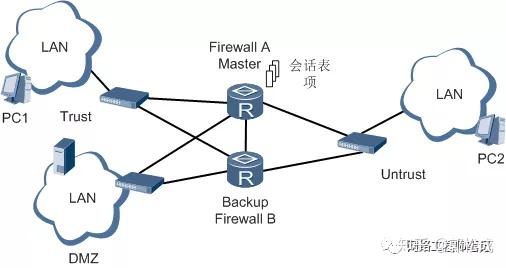
As shown in the figure, Firewall A has created many dynamic session tables on board as Master equipment and undertakes all data transfer tasks; while Firewall B is back-up without any traffic flow.
If Firewall A fails or the associated link is compromised, Firewall B will switch to a new Master and start performing transmission tasks.
If the session list item is not backed up to Firewall B before the status switch, all sessions previously passed Firewall A will be unable to communicate because they do not match the Firewall B schedule and will cause business disruption.
In order to achieve a failure of the Master firewall, it is possible to be smoothly replaced by the Backup firewall, with real-time backups of session tables and status information between the Master and Backup walls; current firewall masters are able to obtain backup and synchronization through HSB mechanisms for conversational table and state information between Master and Backup firewalls.
Status requirements for firewall mains
Firewall message not consistent path map
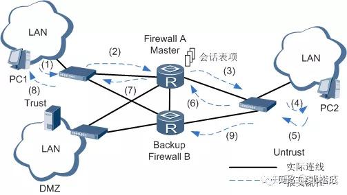
The VRRP status of the firewall needs to be consistent, which means that several interfaces on the firewall and connected to each safety area are in the same state, i.e. both primary or stand-by state.
Assuming that the VRRP status of Firewall A and Firewall B is consistent, i.e. all Firewall A interfaces are primary and all Firewall B interfaces are stand-by. At this time, PC1 in the Trust region access to PC2 in the Untrust area with transmission routes of (1)-(2)-(3)-(4). Firewall A transmits a visit to the report, dynamic generation of session forms is made. When PC2 returns reports arrive through (5)-(6)-(7)-(8)/Firewall A, smooth return and communication is achieved by matching the session schedule items.
Assuming that the VRRP status of Firewall A and Firewall B is not consistent, e.g. the interface between Firewall B and the Trust area is standby but the interface with the Untrust region is primarily used, PC1 will dynamically generate session tables on Firewall A after reaching PC2 via Firewall A device. PC2 returns by route (5)-(9). At this time, since there are no schedules for corresponding data flows on Fairwall B, Firewall B will abandon the paper without other filtering rules allowing passage.
In addition, the downlink to the switch can ensure its reliability through the switch ‘ s SmartLink while ensuring that downlinks fail between two firewall devices by means of a direct link that will allow corresponding traffic to the opposite end of the firewall.
Note:
Firewalls do not support double-heat backup of user configuration data, and users must ensure consistency in the distribution of data on both firewalls.
• The two sets of backup equipment must be identical in size, with the same memory, CPU and feature configuration, otherwise complete backup cannot be guaranteed.
The software version of the two back-up devices must be consistent.
The backup interface cannot be identical to the firewall business interface and must use a dedicated back-up interface, which is no longer involved in data forwarding.
The main firewall under the asymmetric route pattern is not supported, and a single stream must pass through the same equipment.
The synchronization of statistical information is not supported, but only the session information master for TCP/UDP.
未经允许不得转载:萌萌Apprentissage » Cybersecurity -- firewalls -- common cyber attacks


 learn NMAP

